
Natural stone rainscreen cladding is now more popular than ever. Hardly surprising as stone is one of the most sustainable building products on the planet. It is extremely durable, cost effective and available.
However, as with all rainscreen a successful specification must consider a number of factors including the appearance of the stone, the panel geometry, the rainscreen system, supporting structure, insulation, cavity ventilation, fire strategy, installation tolerances and long-term maintenance.
All influence the performance of the finished façade.
The following guide sets out the principal considerations to address before a natural stone rainscreen system is specified.
1. Choosing the Right Natural Stone
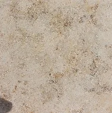





The choice of stone establishes the architectural character of the façade, but it also affects panel dimensions, fixing design and long-term durability. Stone should therefore be selected on the basis of both appearance and verified technical properties.
Geological characteristics and suitability
Natural stone is formed through different geological processes, producing materials with different mineral compositions, structures and mechanical properties. These differences influence how a stone behaves when cut, drilled, slotted, exposed to moisture or subjected to repeated temperature changes.
When assessing a proposed stone, we need to consider:
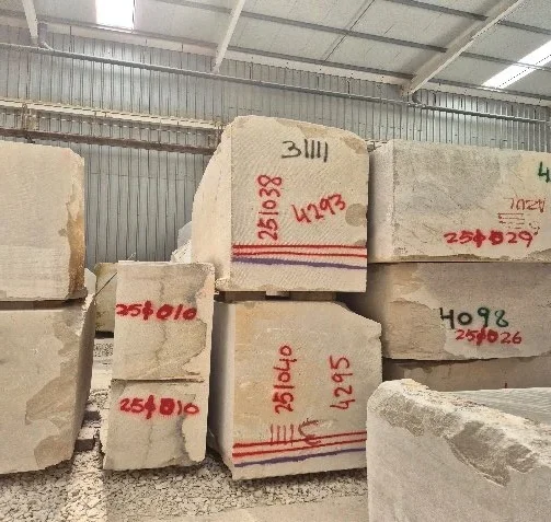
- Mineralogy and structure: Grain size, bedding, foliation, veins, fissures and other natural features can influence strength and the direction in which the stone should be cut.
- Consistency: Establish the extent of variation between blocks, batches and quarry faces. A stone that looks consistent in a small sample may exhibit greater variation across a full façade.
- Representative testing: Obtain test data for the actual stone source and proposed orientation, rather than relying solely on generic values for a named stone type. All stone should be tested on the recommended rainscreen system (wind loading/impact etc) but also on its own for durability.
The stone supplier should be able to provide relevant declared characteristics and test information. BS EN 1469 that addresses requirements for natural stone slabs used for internal and external cladding, including product characteristics, Testing procedures and conformity information. It does not, by itself, cover the installation design of the complete façade.
Limestone, sandstone, granite and other stone types
Different stone families offer different combinations of appearance, workability and durability.
- Limestone: Often selected for its restrained colour palette, fine texture and architectural versatility. Its performance varies considerably with mineral composition, porosity, bedding and the presence of clay or other constituents.
- Sandstone: Can provide a distinctive grain and natural texture, with colours ranging from buff to red and grey. Bedding orientation, pore structure and resistance to moisture and frost should be assessed carefully.
- Granite: Generally associated with crystalline textures and a wide range of colours. Its strength and durability can make it suitable for demanding applications, but its density, porosity and weight must be considered in panel and support design.
- Slate and other stones: May be suitable for particular architectural effects, but their natural cleavage, anisotropy and product format require specific consideration.
These are broad material descriptions, not design values. The performance of an individual stone must be established from its own characteristics and intended use.
Colour, texture, finish and natural variation

Stone is a natural material, so variation in colour, veining, grain, fossil content and texture is an inherent and, we would argue, desirable part of its appearance. The specification should define the intended visual range.
A useful process is to agree:
- A representative sample showing the expected colour and texture range. This can often involve a visit to the production yard to view larger panels and not rely on a few small desk samples.
- The proposed finish, such as honed, sawn, flamed, bush-hammered or polished.
- Acceptable limits for variation, markings and natural features.
- The intended panel orientation and whether bedding or veining should run consistently.
- A project-specific control samples or agreed sample panel for approval before production.
- A full report documenting the agreements can be produced
A full-size sample panel is particularly valuable where panel size, joint width, finish and fixing details combine to create the overall façade appearance.
Durability, porosity and environmental exposure
Stone selection should reflect the conditions to which the façade will be exposed. Relevant considerations include:
- Water absorption and the rate at which the stone dries.
- Freeze-thaw resistance where the stone may become saturated and experience freezing conditions.
- Salt exposure, including coastal environments and de-icing salts.
- Atmospheric pollution and potential chemical interaction.
- Biological growth, staining and soiling.
- The effect of the proposed finish on water absorption, cleaning and weathering.
Testing may include water absorption, density, flexural strength and frost resistance, as appropriate to the stone and project. BS EN 12371/2 provide a method for assessing the frost resistance and flexural strength of natural stone.
2. Establishing Panel Dimensions and Thickness
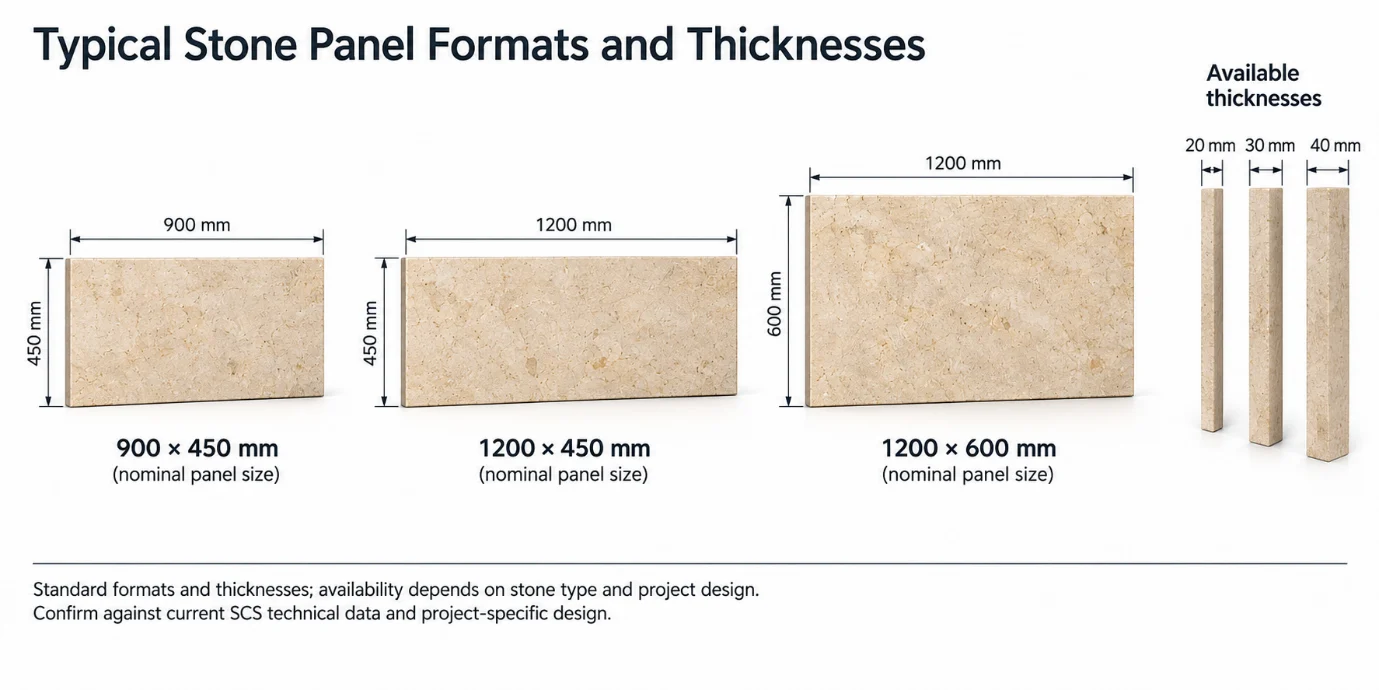
Panel dimensions affect the appearance of the façade, but also determine the loads carried by the façade at any point, the number and position of fixings, handling requirements and installation productivity.
Panel size and weight
The weight of each panel is influenced by its length, height, thickness and the density of the stone. Larger panels can reduce the number of joints and create a more continuous architectural surface, but they may increase:
- Dead load transferred through the support system.
- Wind load carried by each panel and its fixings.
- Handling and lifting requirements.
- The complexity of replacement and access.
Panel dimensions should be developed alongside the structural support strategy, rather than finalised independently. Maximum panel sizes are generally those tested on the rainscreen system and are usually available on company websites. If larger panels are required this will involve further testing which should be advised early so that results can be obtained before full design.
Flexural strength and stone characteristics
Natural stone can be a brittle material. Its capacity to resist bending depends on its material properties, geometry, support conditions, orientation and the presence of natural discontinuities. Its flexural strength can be a very good indicator of a stones suitability.
The design should consider:
- Declared or tested flexural strength to BS EN 12372:2022
- The direction of bedding, veining or other structural features.
- Panel span and support positions.
- Wind loading. Tested to CWCT recommendation
- The effects of handling, transport and installation.
Where a panel incorporates a slot or kerf, the remaining stone section and the local stress concentration around the fixing must be considered. Questions around this can often be resolved by testing.
Fixing positions and edge distances
An established system such as Aztec will have tested the façade at a predetermined geometry. If designing from scratch, fixing geometry is central to the safe performance of a mechanically fixed stone façade. The location of each fixing should be coordinated with the panel dimensions and the stone’s tested characteristics
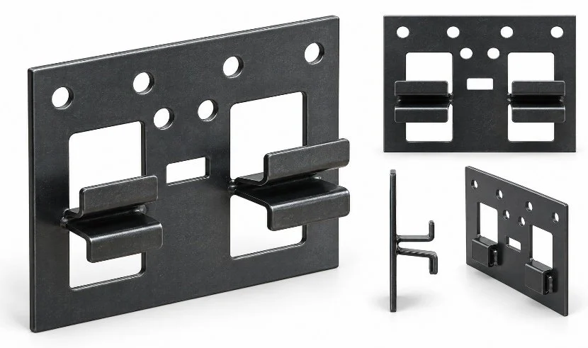
The design should establish:
- The number and position of clips/fixings supporting each panel.
- Required edge distances and residual stone thickness.
- Kerf or slot dimensions and tolerances.
- The load transferred through each fixing.
Balancing architectural intent with structural requirements
The preferred architectural module may not be the most efficient structural module. A practical design process tests the desired panel proportions against stone properties, fixing capacity, wind loading, support spacing, installation access and handling limitations.
Early expert coordination can avoid late changes to panel sizes, joint positions or support locations that would otherwise affect the façade appearance and programme.
3. Selecting the Supporting and Fixing System
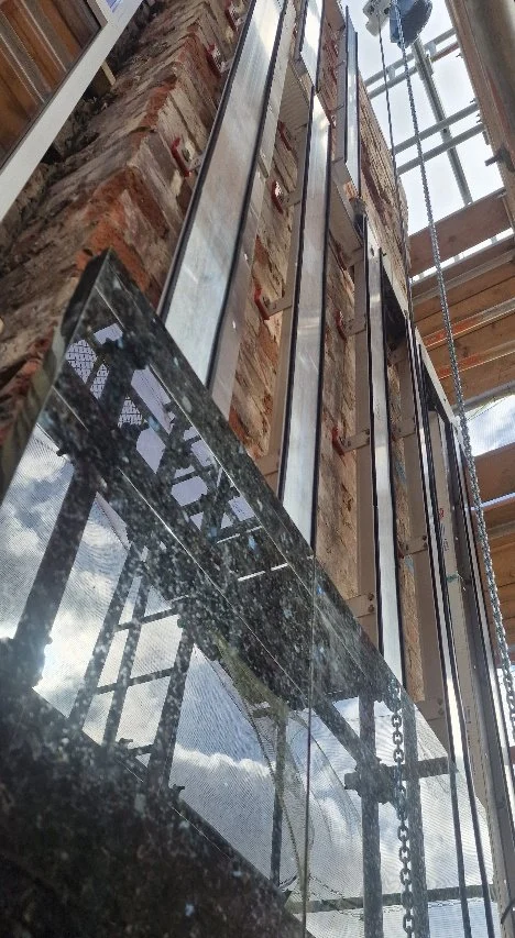
A natural stone rainscreen is a system of interacting components. The stone, clips, rails, brackets, anchors and substrate must be designed to work together under the relevant loads and environmental conditions.
Mechanical fixing principles
Mechanical fixing systems transfer the loads from the stone panels through the fixing components and supporting framework into the building structure.
The design should establish the load path for:
- Dead load: The self-weight of the stone and supporting components.
- Wind load: Positive & negative Pressure on the façade.
- Movement: Thermal movement, structural movement and differential movement between materials.
- Local actions: Loads associated with panel handling, installation, impact or other project-specific conditions.
The fixing arrangement must retain the stone securely while allowing for the movements and tolerances anticipated by the design. It is entirely possible that the supplier can assist with the design of the backing structure to suit the chosen stone and panel sizes. This will take into account local wind ; building orientation etc
Stainless steel brackets, clips and support components
Stainless steel is commonly used for components because of its strength and corrosion resistance. Aluminium is usually used for the rails and brackets for their strength whilst being lightweight. The grade, thickness, geometry, fabrication and fixing method should be appropriate to the design environment, testing and load requirements.
Where a system uses a proprietary clip, the specification should identify the actual component and its intended function. For example, the SCS Aztec arrangement uses a retaining clip engaging machined slots in the stone and fixed to a vertical aluminium T-rail. The clip geometry, slot engagement and screw connection should be represented accurately in project details.
Adjustment and tolerance accommodation
Construction tolerances accumulate across the substrate, brackets, rails, stone panels and fixing components. A support system should provide sufficient adjustment to achieve the intended façade plane and joint alignment without compromising the fixing engagement or structural performance.
The design should define:
- The adjustment available at the bracket-to-substrate connection.
- The permitted rail alignment and support spacing.
- The required installation tolerances.
- How panel thickness and slot-position variation are accommodated.
- How fixed and sliding points, where used, manage movement.
Substrate suitability and structural coordination
The supporting wall must be capable of receiving the loads transferred by the façade brackets. The design team should establish the substrate type, strength, condition, thickness and fixing zones.
For masonry or concrete, the anchor selection and embedment must be compatible with the actual substrate and design actions. It maybe that a pull out test is required before design can be started. For framed construction, the bracket load path must connect to suitable structural members or designed support zones—not simply to an unverified sheathing layer.
Bracket positions should be coordinated with:
- Structural framing and slab edges.
- Movement joints.
- Window and door openings.
- Insulation and cavity barriers.
- Services and other concealed components.
The importance of system-specific design
A generic rainscreen detail cannot demonstrate the performance of every proprietary system. Clip geometry, rail section, bracket arrangement, anchor type, panel dimensions and stone characteristics all influence the design.
Use system-specific technical information and project calculations, and ensure that any change to the specified components is reviewed for its effect on the complete assembly.
BS 8298-4 provides recommendations for the design, installation and maintenance of natural stone cladding on rainscreen support systems.
4. Understanding the Façade Build-Up
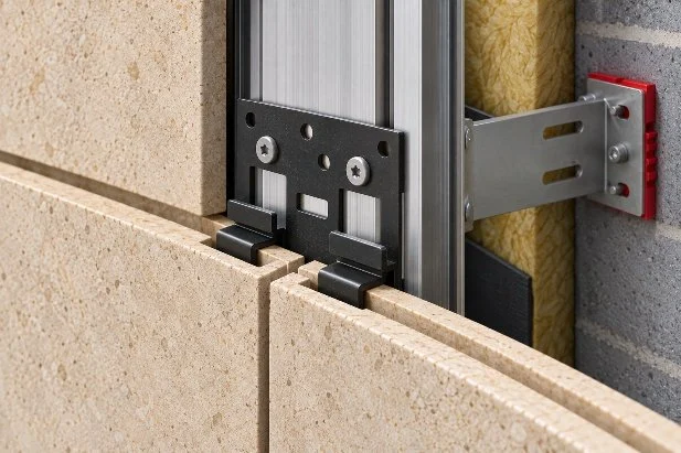
A typical natural stone rainscreen façade consists of external stone panels, a ventilated cavity, insulation, vapour membrane, a supporting framework and the building’s backing wall. Additional layers and components may be required to meet the project’s structural, thermal, moisture and fire requirements.
Structural substrate
The backing wall provides the primary support for the façade brackets and anchors. It may be concrete, masonry, steel framing or another engineered construction.
The specification should identify the substrate and establish the fixing design basis. Substrate tolerances and construction sequencing are important: the façade support system should not be expected to compensate for uncontrolled deviations in the underlying structure.
Insulation and thermal performance
The insulation layer contributes to the building’s thermal performance and can influence condensation risk, energy use and occupant comfort.
The design should address:
- Required thermal transmittance (U-value).
- Insulation type, thickness and declared performance.
- Fixing and retention method.
- Continuity around brackets, slab edges and openings.
- Thermal bridging through metal support components.
- Compatibility with the cavity and fire strategy.
- Moisture behaviour and the backing wall’s vapour-control strategy, where relevant.
The thermal design should assess the complete wall build-up, including the effect of brackets and other repeating thermal bridges.
Ventilated cavity
The cavity separates the external stone from the backing construction and provides a route for drainage and ventilation where designed as a ventilated rainscreen. It is a very functional part of the façade design.
Its depth and configuration should be coordinated with the support system, insulation, openings and fire barriers. The cavity must remain sufficiently clear for its intended function, taking account of:
- Brackets, rails and clips.
- Construction tolerances.
- Insulation bulging or displacement.
- Debris and mortar droppings.
- Cavity barriers and fire-stopping components.
- Drainage and ventilation openings.
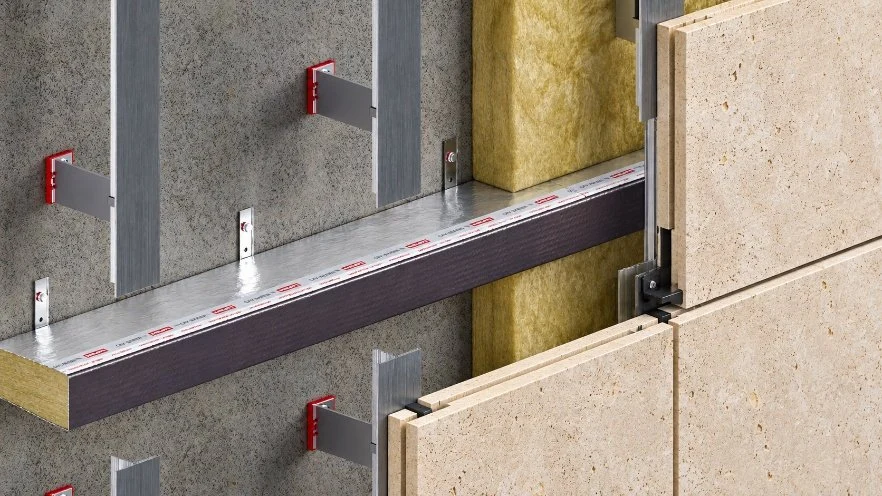
Cavity barriers and fire strategy
Cavity barriers are intended to restrict fire and smoke movement through concealed cavities. Their locations and performance should be determined by the project fire strategy and the applicable building regulations.
Typical locations requiring consideration include:
- Around window and door openings.
- At compartment floors and walls, where required.
- At cavity edges and changes in construction.
- At other locations identified by the fire strategy.
The selected barrier must be compatible with the cavity width, supporting construction, movement and ventilation requirements. Its installation and fixing details should be coordinated with the façade system so that it does not obstruct drainage or compromise the intended cavity function.
Weather protection and drainage
The external stone is the first line of weather protection, but a rainscreen façade should be designed on the understanding that some water may pass through joints.
The backing wall and associated membranes or flashings should therefore provide the required secondary weather protection. Details should allow water to drain outward and prevent water from being directed into vulnerable parts of the construction. Water vapour is moved out of the cavity by way of air movement up and down behind the stone façade. This is a very efficient method of preventing water ingress to a building
Pay particular attention to:
- Base-of-wall drainage and ventilation.
- Window and door heads, jambs and sills.
- Parapets, copings and roof interfaces. Allowing ventilation.
- Changes in façade plane.
- Penetrations and service interfaces.
- Junctions with adjacent cladding materials.
5. Fire Performance and Regulatory Considerations
Reaction-to-fire classification of materials
Reaction-to-fire classification describes how a product contributes to fire development under specified test conditions. The relevant classification and evidence should be established for each material where required by the project and applicable regulations through BS EN 13501-1
Natural stone and indeed the full Aztec system may have a favourable reaction-to-fire classification being A1, but that does not establish the fire performance of insulation, membranes, support components, cavity barriers or the complete wall assembly.
Façade system performance and project-specific fire strategy
The fire strategy should consider the building’s use, height, occupancy, compartmentation, external wall construction and applicable regulatory requirements.
It should establish the relevant performance requirements and identify the evidence needed to demonstrate compliance. The project team should distinguish between:
- Product reaction-to-fire classification. Such as BS EN 13501-1:2018
- Fire resistance of individual elements or barriers.
- Performance of the complete external wall construction.
- The project-specific fire strategy and regulatory assessment.
In England, Approved Document B provides statutory guidance on fire safety, including external fire spread and cavity-barrier provisions. This is practical guidance approved by the Secretary of State on how to meet the legal requirements of the Building Regulations 2010 (specifically Part B). The applicable edition and amendments should be checked for the project’s location, building type and regulatory route.
Cavity-barrier positioning
Cavity-barrier locations should be shown clearly on the façade drawings and coordinated with the stone support system. The design should account for the barrier’s fixing, continuity, movement capability and interface with openings and compartment lines including the need for barriers to remain effective despite movement and failure of adjacent components.
Relevant testing, assessment and regulatory documentation
The specification should identify the documentation required for the project, which may include:
- Product data and reaction-to-fire classifications.
- Relevant test reports and assessment documents.
- System-specific design calculations.
- Details of cavity barriers and fire-stopping components.
- Fire strategy drawings and supporting rationale.
- Evidence required by the building control or building safety process.
Testing and assessment should be interpreted within their stated scope. Evidence for one material, component or wall arrangement should not be assumed to apply automatically to a different build-up.
6. Designing for Installation
A technically sound façade design must also be practical to set out, assemble, inspect and complete on site. Installation considerations should be resolved before the system is released for manufacture.
Setting-out and dimensional tolerances
The setting-out strategy should establish the façade datum, panel module, joint widths (usually 6mm) , rail positions and bracket locations.
The design should account for tolerances in:
- The primary structure and backing wall.
- Bracket positions and adjustment.
- Rail straightness and alignment.
- Stone panel dimensions and thickness.
- Slot or kerf positions.
- Joint widths and façade plane.
Installation sequence
The installation sequence should be considered during design, particularly where stone panels engage with mechanical clips or where access to fixings becomes restricted after adjacent panels are installed.
A typical sequence may involve:
- Surveying and confirming the substrate.
- Setting out bracket locations.
- Installing and checking brackets and anchors.
- Installing, aligning and securing the vertical support rails.
- Installing insulation and associated membranes in the agreed sequence.
- Installing cavity barriers and fire-stopping components at the required stages.
- Installing stone panels and engaging the specified mechanical fixings.
- Checking alignment, joints, fixing engagement and completed details.
The precise sequence must follow the selected system’s installation requirements and the project’s method statement.
Access and handling
Panel weight, size, lifting points, site access and working-platform arrangements should be established early. Larger panels may require mechanical lifting equipment or specialist handling procedures.
The design should also consider safe access for installation and future replacement, particularly at high-level locations, corners, soffits and areas adjacent to other building elements.
Coordination with other trades
The façade package interfaces with structural works, windows, roofing, insulation, fire-stopping, waterproofing and services. Clear responsibility should be assigned for each interface.
Coordination drawings and installation sequencing should identify where one trade’s work must be completed or inspected before another trade closes the cavity or installs the stone.
Quality control and inspection
Inspection should take place at stages when key components remain visible and accessible. Relevant checks may include:
- Substrate condition and fixing locations.
- Anchor installation and required records.
- Bracket type, position and adjustment.
- Rail alignment and connection.
- Insulation continuity and retention.
- Cavity-barrier location and installation.
- Stone condition, dimensions and machined slots.
- Clip engagement and fixing security.
- Joint alignment and finished façade appearance.
The inspection and test plan should identify hold points, acceptance criteria, records and responsibility for sign-off.
7. Maintenance, Durability and Whole-Life Performance

Natural stone can provide a long service life, but the performance of the façade depends on the stone, support system, detailing, exposure and maintenance regime.
Inspection and maintenance considerations
The maintenance strategy should reflect the building’s location, height, exposure and access arrangements. Periodic inspections may consider:
- Visible cracking, spalling or damage to stone.
- Displacement or changes in panel alignment.
- Corrosion or deterioration of accessible metal components.
- Blocked drainage or ventilation openings.
- Condition of sealants, flashings and adjacent materials.
- Evidence of staining, biological growth or surface deterioration.
Inspection intervals should be established for the project and adjusted in response to observed condition and exposure.
Replacement of individual panels
A key consideration in a mechanically fixed rainscreen is whether individual panels can be removed and replaced without unnecessary disturbance to surrounding areas.
The design should consider the access required to release the fixing, the removal route, any temporary support and the sequence for reinstalling adjacent panels. Replacement procedures should be documented where panel removal is not straightforward.
Long-term material performance
Stone may weather and develop changes in colour or surface character over time. The specification should distinguish between expected natural weathering and unacceptable deterioration.
Metal components should be selected for the environmental exposure and designed to avoid incompatible material combinations or conditions that could accelerate corrosion. The support system should also accommodate the movements anticipated over the building’s service life.
Repairability and potential for reuse
The façade design can support future repair and reuse by:
- Using mechanically fixed panels.
- Recording panel sizes, stone source, finish and fixing details.
- Retaining installation and inspection records.
- Avoiding unnecessary damage to panels during maintenance.
- Identifying whether removed stone can be reused or repurposed.
The potential for reuse is huge and will depend on the condition of the stone, the method of removal, the integrity of machined fixing zones and the requirements of the subsequent application.
8. The Specification Checklist
When specifying a natural stone rainscreen system, establish the following information and confirm who is responsible for providing it. This checklist is available in the download section of our website.
Closing note
Early coordination between the architect, façade designer, structural engineer, stone supplier, system supplier and installer helps align the architectural intent with the structural, thermal, fire, installation and maintenance requirements of the building.